OS Fans
400, 500, 630, 800 and 1000
Content
- Performance characteristics of the fans
- Description
- Use
- Working conditions
- Main connection dimensions
- Designation
- Performance characteristics of the fans
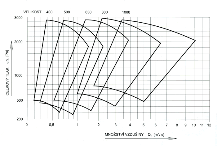
Performance charactieristics of the individual fans
OS 400
OS 500
OS 630
OS 800
OS 1000
- Description
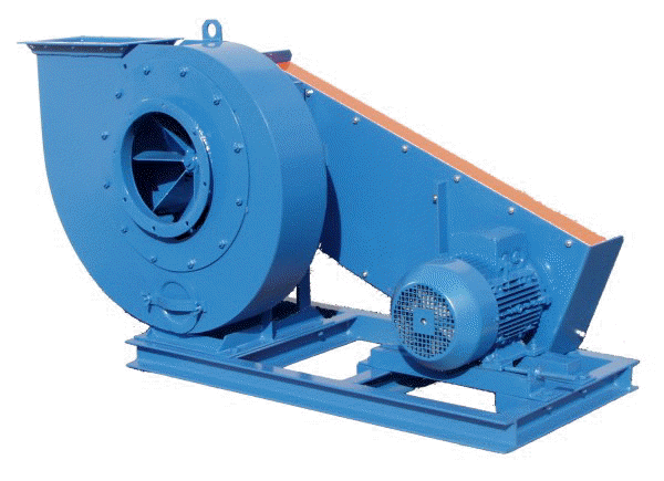
OS single inlet fans, according to PS 12 3237 are radial transport pressure fans, which are produced in sizes 400, 500, 630, 800 and 1000. They are driven by an electric motor via belt drive, the impeller is mounted overhung on the shaft. To extend the fan power output various ratios with different engine wattages can be selected. Fans are available with either a bare shaft (without transmission and electric motor) or transfer (complete belt drive and motor). The fan with gear coupling can be ordered on a common frame
.
- Use
Fans are used to transport non-sticking industrial waste in the woodworking industry (sawdust, shavings, textile waste ...), paper mills and similar industries. They can only be used for the transfer of V-belts and for the transport of air without danger of explosion. The fans are not gas-tight and should not be used for the transport of harmful and odorous air mass.
- Working conditions
Fans can transport the above industrial waste or clean air at a temperature range of -20 ° C to + 85 ° C. Fans are suitable for air mass transport of industrial waste and can be placed in environments without the danger of explosion (BNV - CSN 33 2320) at an ambient temperature of -20 ° C to +40 ° C. The fan can be operated only under conditions and with parameters that have been approved by the manufacturer or according to the data plate on the fan.
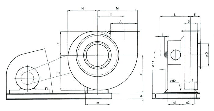
- Main connection dimensions
| Size |
A |
B |
C |
D |
E |
F |
G |
H |
J |
K |
L |
M |
N |
P |
R |
d |
p |
u |
s |
Weight |
| 560 |
160 |
125 |
320 |
315 |
324 |
373 |
66 |
450 |
346 |
598 |
144 |
390 |
420 |
199 |
220 |
12 |
2 |
160 |
33 |
82 |
| 630 |
200 |
140 |
375 |
355 |
388 |
446 |
74 |
580 |
414 |
647 |
153 |
450 |
510 |
215 |
260 |
14 |
2 |
180 |
30 |
124 |
| 800 |
250 |
180 |
470 |
450 |
481 |
557 |
94 |
700 |
519 |
848 |
194 |
560 |
610 |
270 |
280 |
14 |
3 |
160 |
40 |
200 |
Flange connecting dimensions and position of the spiral casing
The position of the volute (spiral) casing is determined when viewed from the side intake.
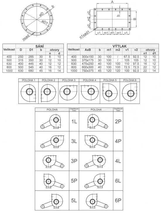
Connecting dimensions of frames of the OS fans
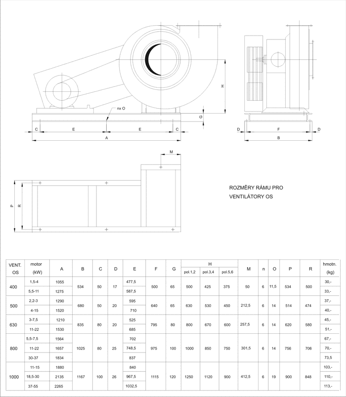
400
|
500
|
630
|
800
|
1000
|
A
|
300
|
375
|
475
|
600
|
750
|
| B |
150
|
175
|
250
|
300
|
375
|
C
|
390
|
485
|
616
|
780
|
970
|
D
|
250
|
315
|
400
|
500
|
630
|
E
|
300
|
375
|
470
|
600
|
745
|
F
|
270
|
335
|
428
|
540
|
670
|
H for position
|
1-2
|
500
|
630
|
800
|
1000
|
1250
|
3-4
|
425
|
530
|
670
|
850
|
1120
|
5-6
|
375
|
450
|
600
|
750
|
900
|
| K |
109
|
122
|
167
|
192
|
234
|
L
|
342
|
413
|
510
|
636
|
722
|
M
|
450
|
560
|
710
|
900
|
1120
|
N
|
330
|
410
|
522
|
660
|
820
|
R
|
65
|
65
|
80
|
100
|
120
|
d1
|
22j6
|
28j6
|
38j6
|
48j6
|
55j6
|
d2
|
14
|
19
|
19
|
24
|
24
|
f
|
37,5
|
155,5
|
201
|
235
|
292,5
|
l
|
50
|
60
|
80
|
110
|
110
|
m
|
275
|
385
|
470
|
550
|
770
|
n1
|
295
|
225
|
250
|
320
|
360
|
n2
|
-
|
270
|
360
|
420
|
520
|
Weight *
|
65
|
104
|
202
|
303
|
521
|
- Designation
An example of the transport fans with free shaft end:
Transport fan with a free shaft – OS 400 - PS 12 3237 . 3
| OS 400 |
type and size |
| PS 12 3237 |
norm number |
3 housing
|
spiral position.
|
An example of the transport fans with coupling :
Transport fan with gear coupling OS 400 - PS 12 3237 . 3L - 4kW - 2350
| OS 400 |
type and size |
| PP 12 3344 |
norm number |
| 3L |
position of spiral housing |
| 4kW |
motor output
|
| 2350 |
Fan revolutions
|