RVI Fans
315, 400, 500, 630, 800, 1000 and 1250
Content
- Performance characteristics of the fans
- Description
- Use
- Working conditions
- Hlavní připojovací rozměry
- Designation
1. Performance characteristics of the fans
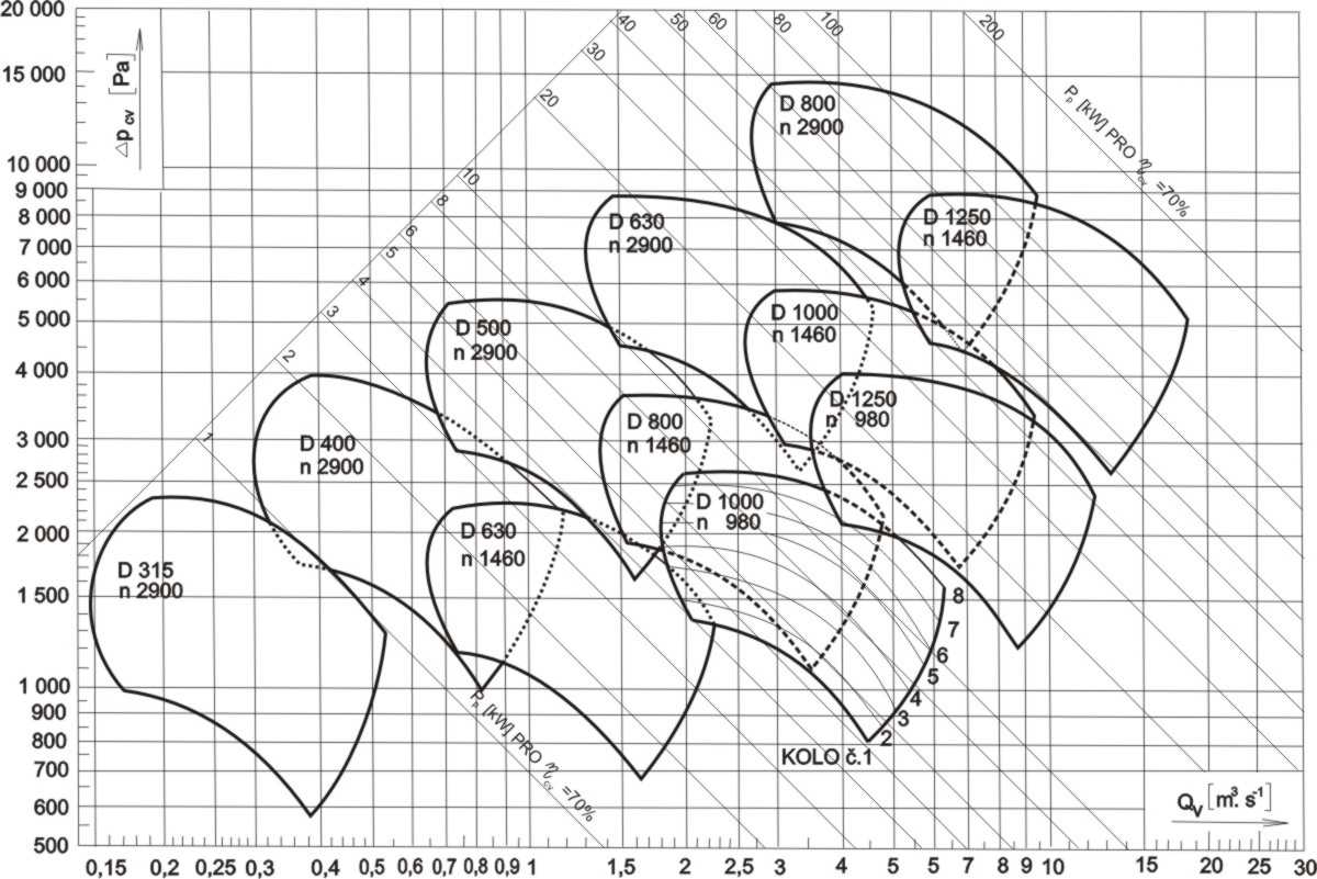
Performance characteristics of the individual fans
2. Description
RVI fans are centrifugal, high pressure single inlet fans of size 315, 400, 500, 630 800, 1000 and 1250. The fans are powered by electric motors to directly or via a flexible coupling. To extend the fan power it is possible with a single size fan to use eight different impellers (1, 2, 3, 4, 5, 6, 7 and 8). Fans do not have power regulation – they must be addressed in the connecting ducts. Fans can anchor directly on the concrete base through isolators or flexibly. Clutch or coupling fans are used at a temperature of transported air above 70 ° C. At a temperature above 100 ° C, the bearing disc mounted on the shaft between the volute (spiral) casing and bearing are cooled by a refrigerant. Fans are manufactured in the standard version, moreover size 630 is also made in the armoured version (i.e. reinforced impeller and spiral casing reinforced with a removable cartridge).
3.Use
Fans of standard design are used to transport clean or mild, non-abrasive dust polluted air. Armoured fans are used to transport air mass with abrasive additives. Fans can be used for transport of gaseous, explosive fluids of corrosive nature, air mass containing fibrous dust and gaseous fluid with impurities, which could cause clogging. Fans are not gas-tight and should not be used for the transport of harmful and odorous air mass.
Fans of the RVI series are very suitable for ventilation and the most common types are RVI 500 and RVI 630
4. Working conditions
Direct fans can be used to transport clean air without abrasive particles at temperatures from -20 ° C to +70 ° C. Fans on coupling can transport clean air without abrasive particles at a temperature of -20 ° C to +250 ° C. Fans are suitable for air mass transport and placement in an environment without the danger of explosion (BNV-CSN 33 2320), at an ambient temperature of -20 ° C to +40 ° C.
5. Main connection dimensions
RVI direct
315
|
400
|
500
|
630
|
800
|
1000
|
1250
|
A
|
180
|
225
|
280
|
355
|
450
|
560
|
710
|
| B |
100
|
110
|
140
|
180
|
225
|
280
|
355
|
C
|
250
|
317
|
402
|
498
|
635
|
790
|
990
|
D
|
180
|
225
|
280
|
355
|
450
|
560
|
710
|
E
|
211
|
260
|
330
|
411
|
528
|
652
|
821
|
F
|
302
|
377
|
475
|
586
|
748
|
930
|
1169
|
G
|
84
|
90
|
107
|
126
|
117,5
|
145
|
-
|
H
|
375
|
465
|
580
|
730
|
925
|
950
1150**
|
1200
1450**
|
J
|
257
|
319
|
403
|
496
|
633
|
786
|
989
|
K
|
428
|
565
|
730
|
921
|
932
|
1045
|
1415
|
L
|
120
|
120
|
150
|
180
|
194
|
230
|
325
|
M
|
294
|
370
|
460
|
580
|
900
|
1100
|
1450
|
N
|
324
|
400
|
490
|
620
|
960
|
1160
|
1500
|
P
|
186
|
214
|
257
|
285
|
335
|
395
|
-
|
d
|
14
|
14
|
14
|
14
|
19
|
19
|
19
|
| p |
2
|
2
|
2
|
3
|
3
|
3
|
4
|
u
|
120
|
160
|
200
|
200
|
160
|
160
|
300
|
s
|
17
|
35
|
42
|
20
|
70
|
70
|
-
|
| Weight * |
35
|
52
|
101
|
200
|
410
|
595
610**
|
950
965**
|
* Weight without motor
** To turn the spiral housing through 0-45°
RVI on coupling
315
|
400
|
500
|
630
|
800
|
1000
|
1250
|
A
|
180
|
225
|
280
|
355
|
450
|
560
|
710
|
| B |
100
|
110
|
140
|
180
|
225
|
280
|
355
|
C
|
250
|
317
|
402
|
498
|
635
|
790
|
990
|
D
|
180
|
225
|
280
|
355
|
450
|
560
|
710
|
E
|
211
|
260
|
330
|
411
|
528
|
652
|
821
|
F
|
302
|
377
|
475
|
586
|
748
|
930
|
1169
|
G
|
85 |
63 |
78
|
99
|
117,5
|
145
|
182,5 |
H
|
375
|
465
|
580
|
730
|
925
|
950
|
1200
|
J
|
257
|
319
|
403
|
496
|
633
|
786
|
989
|
K
|
919
|
1172
|
1451
1571
|
1370
1880
|
1917
|
2375
|
2508
|
L
|
120
|
120
|
150
|
180
|
153
|
230
|
325
|
M
|
294
|
370
|
460
|
580
|
450 |
1100
|
1450
|
N
|
324
|
400
|
490
|
620
|
510
|
1160
|
1500
|
P
|
-
|
-
|
-
|
-
|
320 |
390
|
470 |
| |
- |
- |
- |
- |
260 |
260 |
750 |
d
|
14
|
14
|
14
|
14
|
18 |
19
|
19
|
| p |
2
|
3
|
3
|
2
2
|
4 |
5 |
5
|
u
|
320 |
320
|
370 |
500
700 |
375
|
375
|
375 |
s
|
50 |
48
|
48
108 |
51
101
|
50 |
60 |
60 |
| Weight * |
91 |
133
|
215
|
320
440 |
675 |
1065 |
1480 |
* Weight without motor
Connecting dimensions of flanges

Dimensions of the suction flange
|
Discharge flange dimensions
|
D
|
D1
|
bxs
|
n
|
d
|
315
|
180
|
215
|
30x4
|
8
|
10
|
400
|
225
|
260
|
30x4
|
8
|
10
|
500
|
280
|
313
|
30x4
|
8
|
10
|
630
|
355
|
390
|
30x10
|
12
|
10
|
800
|
450
|
495
|
40x10
|
12
|
12
|
1000
|
560
|
605
|
40x10
|
16
|
12
|
1250
|
710
|
760
|
45x12
|
20
|
15
|
|
A
|
B
|
bxs
|
n0
|
d0
|
n1
|
m1
|
v1
|
m2
|
v2
|
315
|
180
|
100
|
30x6
|
8
|
10
|
-
|
-
|
107
|
-
|
67
|
400
|
225
|
110
|
30x6
|
10 |
10
|
1
|
100
|
79,5
|
-
|
72
|
500
|
280
|
140
|
30x6
|
10 |
10
|
1
|
100
|
107
|
-
|
87
|
630
|
355
|
180
|
30x10
|
12
|
10
|
2
|
100
|
94,5
|
-
|
107
|
800
|
450
|
225
|
40x10
|
16
|
12
|
3
|
100
|
97
|
100
|
84,5
|
1000
|
560
|
280
|
40x10
|
18 |
12
|
4
|
100
|
102
|
100
|
112
|
1250
|
710
|
355
|
50x12
|
20
|
15
|
4
|
120
|
140
|
240 |
202,5
|
|
Positions of the spiral housing
The position of the volute (spiral) housing is determined when viewed from the side intake
Flexible deposit of RVI direct fans

| 315 |
80
|
1,1
|
P42
|
4
|
50
|
|
306
|
294
|
84
|
186
|
170
|
-
|
-
|
126
|
90S
|
1,5
|
52
|
|
| 400 |
90L
|
2,2
|
P45
|
4
|
78
|
|
374
|
370
|
89
|
214
|
170
|
-
|
-
|
100L
|
3
|
84,-
|
|
112M
|
4
|
91
|
|
534
|
500
|
132S
|
5,5
|
P46
|
6
|
149
|
|
457
|
460
|
108
|
257
|
220
|
-
|
-
|
132S
|
7,5
|
157
|
|
160M
|
11
|
167
|
|
657
|
160M
|
15
|
175
|
|
630 |
132S
|
5,5
|
P47
|
6
|
247
|
|
685
|
580
|
139
|
285
|
280
|
-
|
-
|
126
|
160M
|
15
|
280
|
|
160L
|
18,5
|
290
|
|
180M
|
22
|
357
|
|
885
|
200L
|
30
|
P66
|
407
|
|
|
146 |
200L
|
37
|
427
|
|
|
225M
|
45
|
487
|
|
|
800
|
160M
|
11
|
P66
|
6
|
486
|
|
815
|
900
|
147
|
335
|
260
|
-
|
-
|
146 |
160L
|
15
|
511
|
|
180M
|
18,5
|
558
|
|
655
|
225M
|
45
|
P67
|
8
|
705
|
|
|
600
|
280
|
250M
|
55
|
795
|
|
|
|
280S
|
75
|
920
|
|
|
|
280M
|
90
|
985
|
|
|
|
315S
|
110
|
1175
|
|
935
|
100
|
315M
|
132
|
|
|
|
|
315L
|
160
|
|
|
|
|
| 1000 |
160M
|
7,5
|
P66
|
8
|
|
|
685 |
1100 |
180
|
395
|
260
|
800
|
280
|
146 |
160L
|
11
|
702
|
|
180L
|
15
|
750
|
|
885 |
200L
|
18,5
|
|
|
|
|
180M
|
18,5
|
|
747
|
|
715 |
180L
|
22
|
P67
|
760
|
|
200L
|
30
|
811
|
|
225S
|
37
|
871
|
|
|
225M
|
45
|
906
|
|
|
250M
|
55
|
1025
|
|
|
| 1250 |
200L
|
18,5
|
P66
|
8
|
|
|
978
|
1450
|
323
|
78
|
750
|
750
|
378
|
146 |
200L
|
22
|
|
|
225M
|
30
|
1328
|
|
250M
|
37
|
P74
|
1406
|
|
240 |
280S
|
5
|
1523
|
|
280M
|
55
|
1580
|
|
250M
|
55
|
1426
|
|
378
|
280S
|
75
|
1583
|
|
280M
|
90
|
1650
|
|
315S
|
110
|
1780
|
|
315M
|
132
|
10
|
1880
|
|
78
|
78
|
315L
|
160
|
2036
|
|
6. Designation
An example of the RVI direct drive fans designation, size 630 with impeller No. 5 and the position of the spiral casing L180 ° :
Fan RVI 630 - 5 N - L180° PP 12 3340.2
| RVI 630 |
type and size |
| 5 |
impeller number |
| N |
version
|
| L180° |
position of the spiral housing |
| PP 12 3340 |
techn. conditions number |
| .2 |
arrangement |